1、其实上面的提示也已经给出了解决或者排除问题的方法,那就是紧接着上面提示的下面,输入命令行:
npm fund
2、然后可以查看提示具体的提示内容,是依赖的打赏捐赠提示,然后再接着输入一行命令:
npm run dev
3、回车就可以了,一般都是开发者捐赠支持的提示,打开一个github的链接之后,会显示需要打赏捐赠的信息,此时如果不想捐赠或者跳过这个提示的话,直接在后面加–no-fund即可,具体命令如下:
npm install –no-fund
1、其实上面的提示也已经给出了解决或者排除问题的方法,那就是紧接着上面提示的下面,输入命令行:
npm fund
2、然后可以查看提示具体的提示内容,是依赖的打赏捐赠提示,然后再接着输入一行命令:
npm run dev
3、回车就可以了,一般都是开发者捐赠支持的提示,打开一个github的链接之后,会显示需要打赏捐赠的信息,此时如果不想捐赠或者跳过这个提示的话,直接在后面加–no-fund即可,具体命令如下:
npm install –no-fund
Edit your feeds.conf.default and add the following to it:
# luci-theme-infinityfreedom
src-git infinityfreedom https://github.com/xiaoqingfengATGH/luci-theme-infinityfreedom.git
Update your build environment and install the package:
$ scripts/feeds update infinityfreedom
$ scripts/feeds install luci-theme-infinityfreedom
$ make menuconfig
Go to LuCI -> Themes, select luci-theme-infinityfreedom, exit, save and build as usual.
在 Linux 开发中我们时常会遇到对于之前进程 kill 掉,然后再运行当前进程或程序的情况,此时我们是不知道需要 kill 的进程号的,那么就需要通过一个 shell 命令组合来实现这个需求。
如下命令可以实现:
ps a | grep -w nameprocess | grep -v grep| cut -c 1-6 | xargs kill -9说明:
ps axu|grep nameprocess | awk '{print "kill -9 "}'1、/etc/passwd
Linux 系统中的 /etc/passwd 文件,是系统用户配置文件,存储了系统中所有用户的基本信息,并且所有用户都可以对此文件执行读操作。
[root@localhost ~]# vi /etc/passwd
#查看一下文件内容
root:x:0:0:root:/root:/bin/bash
bin:x:1:1:bin:/bin:/sbin/nologin
daemon:x:2:2:daemon:/sbin:/sbin/nologin
adm:x:3:4:adm:/var/adm:/sbin/nologin
...省略部分输出...
Linux 系统中默认会有多个的用户,这些用户中的绝大多数是系统或服务正常运行所必需的用户,这种用户通常称为系统用户或伪用户。系统用户无法用来登录系统,但也不能删除,因为一旦删除,依赖这些用户运行的服务或程序就不能正常执行,会导致系统问题。
/etc/passwd每行各字段解释:
每行用户信息都以 “:” 作为分隔符,划分为 7 个字段,每个字段所表示的含义如下:
用户名:密码:UID(用户ID):GID(组ID):描述性信息:主目录:默认Shell
UID 为 0 就代表这个账号是管理员账号。
UID 为1~499代表系统用户(伪用户),此范围的 UID 保留给系统使用。其中,1~99 用于系统自行创建的账号,100~499 分配给有系统账号需求的用户。
UID 为500~65535代表普通用户。通常情况下,Linux 系统默认使用的命令解释器是 bash(/bin/bash),当然还有其他命令解释器,例如 sh、csh 等。
在 /etc/passwd 文件中,大家可以把这个字段理解为用户登录之后所拥有的权限。如果这里使用的是 bash 命令解释器,就代表这个用户拥有权限范围内的所有权限。
lamp:x:502:502::/home/lamp:/bin/bash    //它使用的是 bash 命令解释器,那么这个用户就可以使用普通用户的所有权限。
lamp:x:502:502::/home/lamp:/sbin/nologin   ///如果使用sbin/nologin命令解释器,那么这个用户就不能登录了,sbin/nologin是禁止登录的 Shell
2、/etc/shadow
/etc/shadow 文件用于存储 Linux 系统中用户的密码信息,又称为“影子文件”。/etc/shadow 文件只有 root 用户拥有读权限,其他用户没有任何权限。
$ sudo cat /etc/shadow

root:$6$TBFgG/seGvOG8nOp$LvZXXXXXXXENV2F6SEATplyE1QY33W2buEs10XLi.zQD8iwl.kCwsD.OMQ6WWkmUdu/9RPLHvLYSzMfcLj0:18446:0:99999:7:::
daemon:*:18375:0:99999:7:::
bin:*:18375:0:99999:7:::
sys:*:18375:0:99999:7:::
同 /etc/passwd 文件一样,文件中每行代表一个用户,同样使用 “:” 作为分隔符,不同之处在于,每行用户信息被划分为 9 个字段。每个字段的含义如下:
用户名:加密密码:最后一次修改时间:最小修改时间间隔:密码有效期:密码需要变更前的警告天数:密码过期后的宽限时间:账号失效时间:保留字段当我们通过任意文件下载或者目录穿越下载或者读取到/etc/shadow文件时,可以对shadow中加密的密码进行爆破获取明文密码。
shadow文件加密的密码具有固定格式:
$id$salt$encryptedroot:$6$TBFgG/seGvOG8nOp$LvZXXXXXXXENV2F6SEATplyE1QY33W2buEs10XLi.zQD8iwl.kCwsD.OMQ6WWkmUdu/9RPLHvLYSzMfcLj0
id=6,即使用SHA-512哈希算法
salt=TBFgG
encrypted=seGvOG8nOp$LvZXXXXXXXENV2F6SEATplyE1QY33W2buEs10XLi.zQD8iwl.kCwsD.OMQ6WWkmUdu/9RPLHvLYSzMfcLj0我们可以直接使用 john 去破解 shadow 文件:
$ sudo apt install john    //安装John the Ripper

$ john

John the Ripper password cracker, version 1.8.0

Copyright (c) 1996-2013 by Solar Designer

……

$ sudo john ./shadow //暴力破解获取的shadow文件中的账号密码1、分析
检测到时钟偏差,主要是两个设备系统之间的时间上存在差距,导致编译失败。
2、解决
将所有文件都重新touch一遍,更新到本地系统的时间,再make就没问题了。
find ./ -type f |xargs touch
目前市面上按物理规格来看,常见的SD卡有三种:
标准的SD卡,这种卡比较大,在有些相机或者PC电脑上会使用;
第二种是miniSD,这种卡我没怎么使用,不作详述;
最后一种是叫TF卡,也称mirco SD,这种卡比较小,是我们最常接触的,像我们的手机里面使用的就是这种卡。很多人基本上都管我们手机使用的那种卡叫SD卡,这样的叫法实际上不够准确,更准确应该是叫TF卡,但是不管怎样,都没人会去计较,能理解就行。
本文中,如果我说SD卡,都是泛指这三类SD卡,除非特意说明。并且如果特指,我会使用标准SD卡或者TF卡等名称代替。
Capacity of Memory
SD卡按容量(Capacity)分类,可以分为标准容量卡、高容量卡,扩展容量卡,详细如下:
Standard Capacity SD Memory Card (SDSC): 这种卡容量小于等于2GB
High Capacity SD Memory Card (SDHC): 这种卡容量大于2GB,小于等于32GB
Extended Capacity SD Memory Card (SDXC):这种卡容量大于32GB, 小于等于2TB
如果你买了一张16G或者32G的SD卡,你会发现SD卡上面印有”HC”字样,代表该卡是SDHC卡,同理,64G的SD卡上面印着”XC”,表示SDXC卡
Voltage range
SD卡按供电范围划分,分两种:
High Voltage SD Memory Card: 操作的电压范围在2.7-3.6V
UHS-II SD Memory Card: 操作的电压范围VDD1: 2.7-3.6V, VDD2: 1.70-1.95V
UHS-II类型的卡参考协议文档: SD Specifications Part 1 UHS-II Simplified Addendum
Bus Speed Mode (using 4 parallel data lines)
SD卡按总线速度模式来分,有下面几种:
Default Speed mode: 3.3V供电模式,频率上限25MHz,速度上限 12.5MB/sec
High Speed mode: 3.3V供电模式,频率上限50MHz,速度上限 25MB/sec
SDR12: UHS-I卡, 1.8V供电模式,频率上限25MHz,速度上限 12.5MB/sec
SDR25: UHS-I卡, 1.8V供电模式,频率上限50MHz,速度上限 25MB/sec
SDR50: UHS-I卡, 1.8V供电模式,频率上限100MHz,速度上限 50MB/sec
SDR104: UHS-I卡, 1.8V供电模式,频率上限208MHz,速度上限 104MB/sec
DDR50: UHS-I卡, 1.8V供电模式,频率上限50MHz,性能上限 50MB/sec
UHS156: UHS-II RCLK Frequency Range 26MHz – 52MHz, up to 1.56Gbps per lane.
SDR(Single Date Rate), 一个周期只能采集一次数据,即一个bit,由于SD卡是4条数据线并行传输,所以一个周期能传输4bit,如果频率是50MHz(即1秒传输次数为50 000 000),那么1秒能传输的数据量为25MB(这里1MB为1 000 000 Byte)。所以这就是为什么各种SDR模式里面,频率上限是速度上限的两倍。而对于DDR(Double Data Rate),在时钟上升沿和下降沿都可以采集数据,也就是单一周期内可读取或写入2次,因此4条并行数据线在一个周期内能传输8bit。
由于SDHC控制器支持1.8V电平,初始化SD卡时,得知SD也支持1.8V操作,所以像其发送切换电压的命令,但是切换失败。再次尝试初始化时,已不能从SD卡正确获取信息,命令执行超时。
根本原因:SDHC控制器和SD卡座之间添加了电平转换芯片,SDHC的工作电压为1.8V,SD卡座的工作电压为3.3V,SD卡切换为1.8V操作模式时,肯定无法正常工作,因为外部电压是3.3V。
参考文档Documentation/devicetree/bindings/mmc/mmc-controller.yaml,在SDHC控制在设备树节点中添加属性no-1-8-v,如下:
  no-1-8-v:
    $ref: /schemas/types.yaml#/definitions/flag
    description:
      When specified, denotes that 1.8V card voltage is not supported
      on this system, even if the controller claims it.


&esdhc0 {
    sd-uhs-sdr104;
    sd-uhs-sdr50;
    sd-uhs-sdr25;
    sd-uhs-sdr12;
    no-1-8-v;
    status = "okay";
};
1、异常关机,启动报错
/dev/sdb1 contains a file system with errors, check forced.
2、修复测试
fsck -C fd -N /dev/sdb1
提示:
[/sbin/fsck.ext2 (1) -- /dev/sdb1] fsck.ext2 -C0 /dev/sdb1
3、修复执行
fsck.ext2 -C0 /dev/sdb1
基本范例:startActivity(new Intent(Settings.xxx));| 常量 | 含义 |
| ACTION_SETTINGS | 系统设置界面 |
| ACTION_APN_SETTINGS | APN设置界面 |
| ACTION_LOCATION_SOURCE_SETTINGS | 定位设置界面 |
| ACTION_AIRPLANE_MODE_SETTINGS | 更多连接方式设置界面 |
| ACTION_DATA_ROAMING_SETTINGS | 双卡和移动网络设置界面 |
| ACTION_ACCESSIBILITY_SETTINGS | 无障碍设置界面 |
| ACTION_SYNC_SETTINGS | 同步设置界面 |
| ACTION_ADD_ACCOUNT | 添加账户界面 |
| ACTION_NETWORK_OPERATOR_SETTINGS | 选取运营商的界面 |
| ACTION_SECURITY_SETTINGS | 安全设置界面 |
| ACTION_PRIVACY_SETTINGS | 备份重置设置界面 |
| ACTION_VPN_SETTINGS | VPN设置界面,可能不存在 |
| ACTION_WIFI_SETTINGS | 无线网设置界面 |
| ACTION_WIFI_IP_SETTINGS | WIFI的IP设置 |
| ACTION_BLUETOOTH_SETTINGS | 蓝牙设置 |
| ACTION_CAST_SETTINGS | 投射设置 |
| ACTION_DATE_SETTINGS | 日期时间设置 |
| ACTION_SOUND_SETTINGS | 声音设置 |
| ACTION_DISPLAY_SETTINGS | 显示设置 |
| ACTION_LOCALE_SETTINGS | 语言设置 |
| ACTION_VOICE_INPUT_SETTINGS | 辅助应用和语音输入设置 |
| ACTION_INPUT_METHOD_SETTINGS | 语言和输入法设置 |
| ACTION_USER_DICTIONARY_SETTINGS | 个人字典设置界面 |
| ACTION_INTERNAL_STORAGE_SETTINGS | 存储空间设置的界面 |
| ACTION_SEARCH_SETTINGS | 搜索设置界面 |
| ACTION_APPLICATION_DEVELOPMENT_SETTINGS | 开发者选项设置 |
| ACTION_DEVICE_INFO_SETTINGS | 手机状态信息的界面 |
| ACTION_DREAM_SETTINGS | 互动屏保设置的界面 |
| ACTION_NOTIFICATION_LISTENER_SETTINGS | 通知使用权设置的界面 |
| ACTION_NOTIFICATION_POLICY_ACCESS_SETTINGS | 勿扰权限设置的界面 |
| ACTION_CAPTIONING_SETTINGS | 字幕设置的界面 |
| ACTION_PRINT_SETTINGS | 打印设置界面 |
| ACTION_BATTERY_SAVER_SETTINGS | 节电助手界面 |
| ACTION_HOME_SETTINGS | 主屏幕设置界面 |
以跳转到WLAN界面为案例
2.1、普通跳转:就是直接跳到WLAN界面,没有返回键,而且在左上角还有其他一些功能菜单(主要看系统版本和型号)
Intent it = new Intent(Settings.ACTION_WIFI_SETTINGS);
startActivity(it);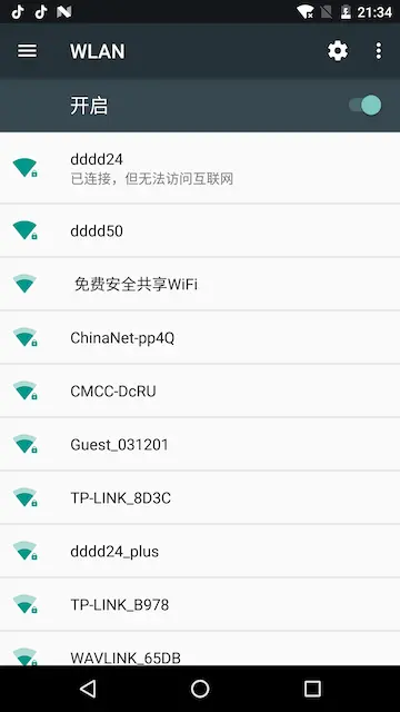
2.2、带有返回键的跳转:可用在部分以安卓为主板,自开发APP为Lancher,不带物理或者虚拟按键栏,又想使用系统自带的wifi功能模块(但是7.0的系统上依旧有左上角功能栏,可能会让客户跳转到其他地方去)
        Intent it = new Intent(Settings.ACTION_WIFI_SETTINGS);
        it.putExtra("extra_prefs_show_button_bar", true);//是否显示button bar
        it.putExtra("extra_prefs_set_next_text", "完成");
        it.putExtra("extra_prefs_set_back_text", "返回");
        //it.putExtra("wifi_enable_next_on_connect", true);
        startActivity(it);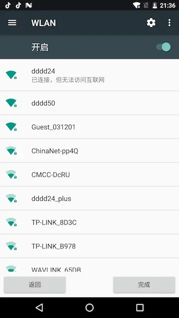
2.3、带有返回键,且只有wifi功能模块的,还可以在result中监听
//注意是这个:WifiManager.ACTION_PICK_WIFI_NETWORK
Intent intent = new Intent(WifiManager.ACTION_PICK_WIFI_NETWORK);
        intent.putExtra("only_access_points", true);
        intent.putExtra("extra_prefs_show_button_bar", true);
        intent.putExtra("wifi_enable_next_on_connect", true);
        startActivityForResult(intent, 1);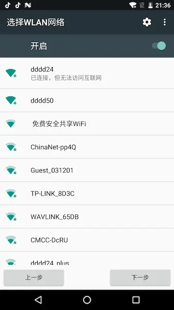
root@somlabs:~# fdisk -l
省略若干


Disk /dev/mmcblk1: 3.7 GiB, 3965714432 bytes, 7745536 sectors
Units: sectors of 1 * 512 = 512 bytes
Sector size (logical/physical): 512 bytes / 512 bytes
I/O size (minimum/optimal): 512 bytes / 512 bytes
Disklabel type: dos
Disk identifier: 0x9de2d76a

Device         Boot Start     End Sectors  Size Id Type
/dev/mmcblk1p0 16384 1628159 1611776 787M 83 Linux假如需要扩展分区为mmcblk0p1
root@somlabs:~# fdisk /dev/mmcblk0
Welcome to fdisk (util-linux 2.29.2).
Changes will remain in memory only, until you decide to write them.
Be careful before using the write command.
Command (m for help): p
Disk /dev/mmcblk1: 3.7 GiB, 3965714432 bytes, 7745536 sectors
Units: sectors of 1 * 512 = 512 bytes
Sector size (logical/physical): 512 bytes / 512 bytes
I/O size (minimum/optimal): 512 bytes / 512 bytes
Disklabel type: dos
Disk identifier: 0x9de2d76a
Device Boot Start End Sectors Size Id Type
/dev/mmcblk1p1 16384 1628159 1611776 787M 83 Linux
这里也看到Start扇区也是16384
Command (m for help): d
把这个分区删除
Partition 1 has been deleted.
Command (m for help): p
列出分区信息Disk /dev/mmcblk1: 3.7 GiB, 3965714432 bytes, 7745536 sectors
Units: sectors of 1 * 512 = 512 bytes
Sector size (logical/physical): 512 bytes / 512 bytes
I/O size (minimum/optimal): 512 bytes / 512 bytes
Disklabel type: dos
Disk identifier: 0x9de2d76a
Command (m for help): n
新建分区Partition type
p primary (0 primary, 0 extended, 4 free)
e extended (container for logical partitions)
Select (default p): p
主分区Partition number (1-4, default 1): 1
分区序号,First sector (2048-7745535, default 2048): 16384
这里要使用起始扇区16384这个值Last sector, +sectors or +size{K,M,G,T,P} (16384-7745535, default 7745535):
默认回车取最大,
Created a new partition 1 of type 'Linux' and of size 3.7 GiB.
Partition #1 contains a ext4 signature.
Do you want to remove the signature? [Y]es/[N]o: n
不改变文件分区信号??
Command (m for help): w
写入生效
The partition table has been altered.
Calling ioctl() to re-read partition table.
Re-reading the partition table failed.: Device or resource busy
The kernel still uses the old table. The new table will be used at the next reboot or after you run partprobe(8) or kpartx(8).root@somlabs:~# rebootresize2fs /dev/mmcblk1p1
resize2fs 1.43.4 (31-Jan-2017)
Filesystem at /dev/mmcblk1p1 is m[ 122.795430] EXT4-fs (mmcblk1p1): resizing filesystem from 201472 to 966144 blocks
ounted on /; on-line resizing required
old_desc_blocks = 1, new_desc_blocks = 1
[ 123.861183] EXT4-fs (mmcblk1p1): resized filesystem to 966144
The filesystem on /dev/mmcblk1p1 is now 966144 (4k) blocks long.df -h
Filesystem Size Used Avail Use% Mounted on
/dev/root 3.7G 499M 3.0G 15% /
devtmpfs 88M 0 88M 0% /dev
tmpfs 248M 0 248M 0% /dev/shm
tmpfs 248M 3.4M 245M 2% /run
tmpfs 5.0M 0 5.0M 0% /run/lock
tmpfs 248M 0 248M 0% /sys/fs/cgroup
tmpfs 50M 0 50M 0% /run/user/01、syslog无法正常工作,处理方法
sudo apt-get install --reinstall rsyslog
chown syslog:adm syslog
sudo service rsyslog restart
2、正确清空syslog方法(不能直接删除)
cat /dev/null > /etc/init.d/syslog
/etc/init.d/rsyslog restart