一、修改DDR初始化阶段波特率
1、查看配置使用哪个DDR驱动
vim $(RKSDK)/rkbin/RKBOOT/RK3568MINIALL.ini 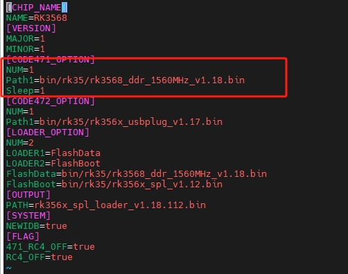
由配置文件可知我们使用的 ddr bin 文件是:rk3568_ddr_1560MHz_v1.18.bin
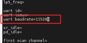
2、修改波特率
修改$(RKSDK)/rkbin/tools/ddrbin_param.txt 波特率参数
3、更新DDR驱动文件
cd $(RKSDK)/rkbin/tools
./ddrbin_tool ddrbin_param.txt ../bin/rk35/rk3568_ddr_1560MHz_v1.13.bin //bin文件的名字需要和 RK3568MINIALL.ini 文件中保持一致。
二、修改uboot波特率
vim configs/rk3568_defconfig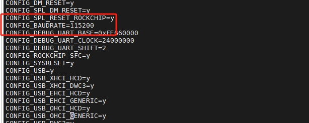
三、修改内核波特率(注意此处openwrt系统)
openwrt是直接通过boot.scr获取内核启动地址及其他配置参数的,所以只需要重新更新波特率参数,重新生成boot.scr就可以了。话说boot.scr是由mkimage工具根据boot.cmd参数生成的。
1、创新boot-bsp.cmd文件
# 写入以下内容
#setenv bootargs console=ttyS0,115200 panic=5 rootwait root=/dev/mmcblk0p2 earlyprintk rw
#setenv bootm_boot_mode sec
#setenv machid 1029
#load mmc 0:1 0x41000000 uImage
#load mmc 0:1 0x41d00000 script.bin
#bootm 0x41000000

# 第一行setenv命令,设定了变量bootargs(启动参数)为:通过tty0和ttyS0串口输出启动信息;启动失败延迟5秒重启,根文件在TF卡的第二分区,可读写;
# 第二行指定了bootm 模式
# 第三行指定解析设备树
# 第四行指定了将压缩后的内核uImage加载到 0x41000000 的位置
# 第五行指定了将 script.bin 加载到 0x41d00000 的位置
# 第六行为从加载地址启动内核的命令

part uuid mmc ${devnum}:3 uuid
setenv bootargs "console=ttyS2,115200 console=tty2 earlycon=uart8250,mmio32,0xfe660000 root=PARTUUID=${uuid} rw rootwait"

load mmc ${devnum}:2 ${fdt_addr_r} rockchip.dtb
load mmc ${devnum}:2 ${kernel_addr_r} kernel.img

booti ${kernel_addr_r} - ${fdt_addr_r}
2、生成boot.scr文件
./tools/mkimage -C none -A arm -T script -d boot-bsp.cmd boot.scr